Today, Wuxi Rihuan Sensing Technology Co., Ltd. will introduce two proximity switches connected in series. Why doesn't the relay engage?
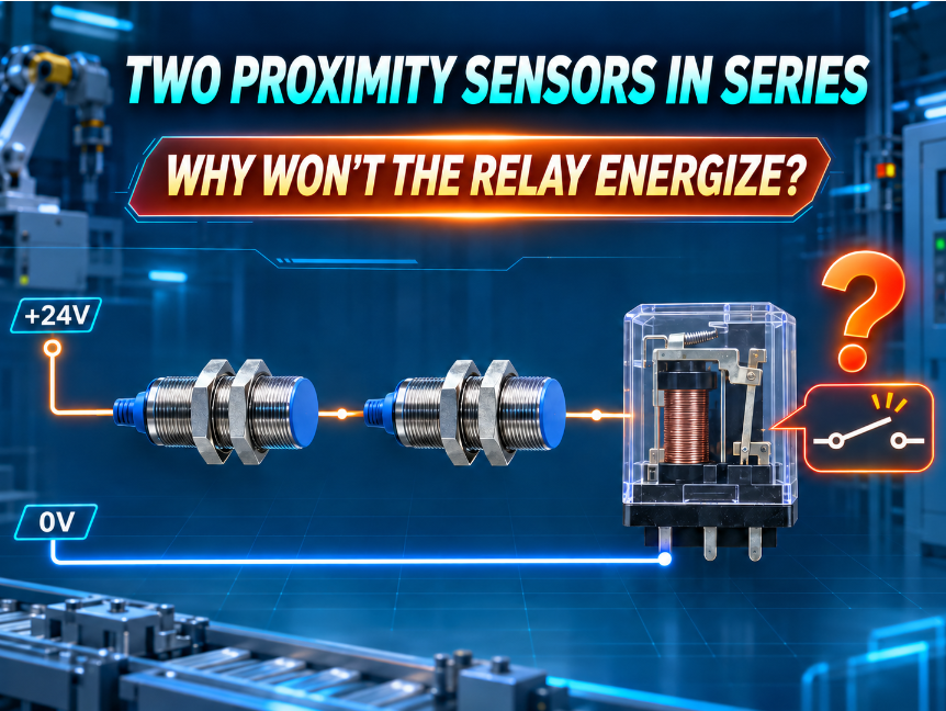
In an automated control cabinet, to save PLC input points or to achieve a simple "AND" logic function, some people will connect two inductive proximity switches in series to drive the same relay coil. Logically, it seems perfect: both switches detect the presence of an object, and the circuit is connected, and the relay engages.
However, when wiring in the field, problems arise: when testing a single switch, it works fine. But when two are connected in series, the relay either remains motionless or makes a "clicking" sound continuously, and the engagement is unstable.
The problem is not with the switches themselves or the relay being broken. Rather, it lies in the fact that each switch consumes a portion of the voltage when conducting (ON).
1. Voltage Drop: The "Hidden Tax" of Series Circuits
Regardless of whether it is NPN or PNP, three-wire or two-wire, the output stage of inductive proximity switches is essentially a semiconductor switch element (transistor or MOSFET). Semiconductor switches, when conducting (ON), are not ideal wires. There is a saturation voltage (voltage drop, Vd) between the two ends.
According to the specifications of mainstream manufacturers, this voltage drop is typically within 2V (for example, some models have a nominal value of ≤ 2V). That is to say, when one switch conducts, the actual voltage received by the load is the power supply voltage minus approximately 2V.
If two switches are connected in series, when both are conducting, the voltage received by the load becomes:
Load voltage = Power supply voltage - 2V (switch 1) - 2V (switch 2) = Power supply voltage - 4V
Assuming the field uses DC 24V power supply, the relay coil's rated voltage is also 24V. According to standard specifications, for the relay to reliably engage, the voltage between its two ends typically needs to reach at least 80% of its rated voltage (i.e., at least 19.2V). In the circuit with two switches connected in series, the load end has a maximum of 24V - 4V = 20V. This is close to the critical value. If the voltage drop of the switches is slightly larger (for example, the actual 2.5V), the voltage drops to below 19V, causing the relay to be in an awkward state of "wanting to engage but not able to" and manifesting as no action or frequent jitter.
2. Not Just Voltage: Hidden Hazards of Minimum Load Current and Leakage Current
In addition to the voltage drop, series connection also touches upon another hard metric of proximity switches: the minimum load current. Some proximity switches require a minimum current to flow in the circuit (for example, several milliamps). If the load (relay) impedance is not suitable after being connected in series, the current does not reach the required level, and the output state of the switch itself may become unreliable.
Furthermore, if using two-wire switches, series connection will also add the influence of leakage current. Each two-wire switch has a tiny leakage current (such as 0.8mA). Although the leakage current does not add when connected in series, the overall circuit's turn-off characteristic becomes more complex, making it more prone to "fail to turn off" or false triggering phenomena.
3. How Many Can Be Connected in Series? Don't Guess
There is no universal number for the maximum number of series connections. It depends on three variables: power supply voltage, the measured voltage drop of the switches, and the minimum engagement voltage of the load.
There is an engineering estimation formula: Power supply voltage - (Number of series connections × Voltage drop of each switch) ≥ Minimum engagement voltage of the load
Taking a 24V power supply, a voltage drop of 2V for each switch, and a minimum engagement voltage of 19.2V for the relay as an example:
24 - (N × 2) ≥ 19.2, solving for N gives N ≤ 2.4. Theoretically, it is勉强 possible to connect 2, but the margin is extremely small. For most 24V systems, connecting two is already close to the limit, and three is basically unable to work reliably.
The more practical suggestion within the industry is: If it is necessary to connect in series, try to keep the number of connections within 2, and definitely measure the voltage at both ends of the load. The official FAQs of manufacturers such as Omron clearly state that when using in series, the actual voltage at the load end must be calculated and confirmed to be higher than the action voltage of the load. For AC two-wire switches, some series even directly indicate "cannot be used in series".
Four. The most reliable solution: Connecting relay contacts in series
If the control logic truly requires that "A and B must both be met before the action is allowed", do not connect the output circuits of the switches in series, but connect the contact circuits of the relays in series.
Specific approach: Let switch A drive relay KA1 alone, and switch B drive relay KA2 alone. Then connect the normally open contacts of KA1 and KA2 in series, and use them to control the final load or input into the PLC. In this way, each switch works in an independent circuit with sufficient voltage, and the output is reliable; while the "AND" function is realized by the passive mechanical contacts, which is not affected by voltage drop and leakage current at all. This is the most mature and least likely to cause problems solution in the field.
Summary
When two proximity switches are connected in series and do not engage, the essence is that the voltage drop across the semiconductor switches accumulates step by step in the series circuit, consuming the voltage margin that the load relies on to operate. In a 24V system, connecting two is already the limit; to connect more, either increase the power supply voltage (make sure the switch can withstand it) or use relay contacts in series to achieve logic.
Rihuan Sensing offers a full range of inductive proximity switches. The product specification clearly indicates the output voltage drop (typical value ≤ 2V), helping users calculate the voltage margin in advance in special wiring scenarios such as series connection or long cables. If you need wiring guidance for two-wire or three-wire products, please follow Rihuan Sensing.
