Today, Wuxi Rihuan Sensing Technology Co., Ltd. will introduce two-wire inductive proximity switches: Why is there no voltage measured when the switch is static, but it "always lights up" when connected to the PLC?
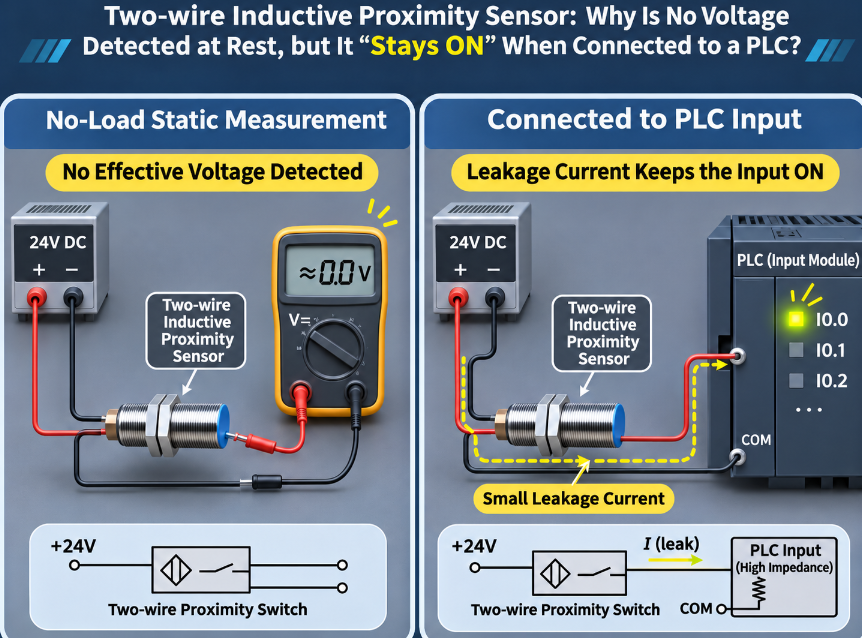
In industrial settings, two-wire inductive proximity switches are highly popular because of their simple wiring (only two wires, connected in series in the circuit). However, many engineers have encountered such strange phenomena: using a multimeter to measure the voltage at the sensor's terminals, the voltage is normal when the sensor is static (not triggered), but once connected to the PLC input point, even without a metal object approaching, the PLC's input indicator light remains constantly on.
The problem is not with the sensor "breaking down", but rather that the two-wire sensor is not completely disconnected in the off state.
1. The "inherent characteristic" of two-wire: There is still leakage current when off
Three-wire sensors have an independent power line and a clean transistor output for the signal line. However, the two-wire sensor only has two wires. It needs to obtain the current required for its own operation through these two wires and also control the load through these two wires.
This means that even when the sensor is off, the internal detection circuit still requires a weak current to maintain the "standby" state. This current is leakage current (Leakage Current). According to the specifications of mainstream manufacturers, the typical leakage current of two-wire DC inductive proximity switches is usually around 0.6mA to 0.8mA.
In a normal load (such as a relay coil) circuit, this leakage current is not enough to make the coil engage, and usually does not cause problems. But the PLC input circuit is a high-impedance, low-current sensitive circuit, the situation is completely different.
2. How does leakage current "trick" the PLC?
The internal of the PLC input point is usually a phototransistor circuit, and the current required for it to conduct is very small (possibly as low as a few milliamperes). When the two-wire sensor is off, the 0.6~0.8mA leakage current will directly flow through the PLC's input circuit.
If the off threshold (OFF Current) of the PLC input point is high, or the input impedance is not low enough, this leakage current may generate a voltage sufficient to make the phototransistor micro-conduct open at the input end. The result is: the sensor does not act, but the PLC detects "signal", and the input indicator light remains constantly on.
This is why, when measuring the voltage between the sensor terminals with a multimeter (with extremely high internal resistance, almost no current taken), it seems normal, but when connected to the PLC (forming an actual current path), problems occur.
3. Minimum load current: Another reverse pit
In addition to leakage current causing "not being able to turn off", two-wire sensors also have a minimum load current (Minimum Load Current) requirement.
The power-taking circuit inside the sensor needs a certain current to maintain normal operation. If the load impedance is too high (such as directly connecting a high-impedance PLC input point, or series-connecting an LED indicator light), the current in the circuit may not reach the minimum load current of the sensor (commonly required to be 2mA to 5mA).
When the sensor is triggered to conduct, due to the low current "consumed" by the load, the internal circuit of the sensor cannot normally establish the working point, resulting in abnormal output voltage (deviating from the saturation voltage drop), and the PLC may not be able to recognize the "ON" signal. Thus, a more confusing phenomenon occurs: it should not be bright when it should be bright, and it should be always bright when it should not be.
How to solve this in the field?
Facing the matching problem of two-wire connected to PLC, there are several mature engineering practices:
Solution 1: Add a discharge resistor (bypass resistor)
Connect a resistor in parallel between the PLC input end (between the sensor signal line and 0V). This resistor serves to divert the leakage current, allowing the 0.6-0.8mA leakage current during turn-off to flow through the resistor instead of being fully fed into the PLC, thereby lowering the input voltage of the PLC below the shutdown threshold. The resistance value and power need to be calculated based on the PLC input voltage and leakage current size to avoid overheating of the resistor.
Alternative 2: Use a relay for isolation
Let the two-wire sensor drive the coil of a relay (with a low coil impedance that can provide sufficient minimum load current and whose leakage current is insufficient to engage), and then use the relay's normally open contacts to connect to the PLC input. The relay performs both electrical isolation and current amplification, completely avoiding the issues of leakage current and impedance matching.
Alternative 3: Directly replace with a three-wire sensor
If the on-site conditions permit, the most thorough solution is to replace with a three-wire (NPN or PNP) sensor. The signal output of the three-wire sensor is an independent transistor switch, with extremely small leakage current during shutdown (usually in the microampere range), and is insensitive to load impedance. It has much better matching with the PLC than the two-wire sensor.
Summary
Root cause of the problem Observation Solution ideas
Leakage current (0.6~0.8mA) PLC input remains constantly lit when not triggered Parallelly install a discharge resistor for分流, or replace with an intermediate relay
Insufficient minimum load current PLC fails to recognize when triggered Ensure the load current is ≥ the sensor's requirement (2~5mA), or add a relay
Two-wire connection to PLC essentially means fighting against the "survival current" of the sensor. Leakage current is essential for its survival but becomes the source of PLC misjudgment; the minimum load current is the prerequisite for its operation but is prone to being "starved" by high-impedance input. Understanding these two parameters and choosing the right matching solution allows two-wire systems to work stably and reliably.
Rihuan Sensing provides a full range of two-wire and three-wire inductive proximity switches. The specification sheet clearly indicates the leakage current and minimum load current parameters, helping users avoid matching risks with PLC during the selection stage. If you need on-site guidance for two-wire connection to PLC, please follow Rihuan Sensing.
