Today, Wuxi Rihuan Sensing Technology Co., Ltd. will introduce to you that the output of OSSD cannot be connected to ordinary relays: there is a conflict between the self-check pulse and the underlying safety circuit.
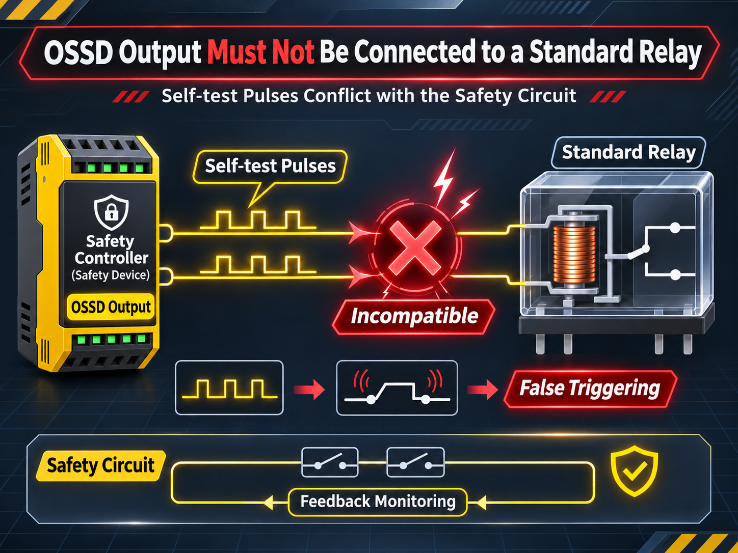
The output terminal of the safety grating is usually labeled as "OSSD" (Output Signal Switching Device). Many on-site engineers, seeing that it outputs a 24V high level, assume it to be a normal PNP signal and directly connect it to an intermediate relay or a normal PLC input point. The result is often: frequent system crashes, errors reported by the safety relay, or simply "it seems to work but the safety level is not up to standard".
The root cause of the problem is not the voltage level, but that the signal output by OSSD contains a "self-check pulse" that ordinary relays cannot recognize.
1. OSSD is not a normal switch; it is a "self-checking output".
The output of a normal NPN or PNP photoelectric sensor is very simple in logic: it conducts when an object is detected and cuts off when no object is detected. The signal is a "clean" high or low level.
OSSD is completely different. It is a self-diagnostic solid-state output designed by the safety grating to achieve a high safety level. OSSD is usually composed of two MOSFETs connected in series and continuously self-monitors during operation. To prove that it is "not broken, not short-circuited, not stuck", OSSD periodically actively generates a very short turn-off pulse and then detects whether the output actually drops as expected.
Take the specifications of the SICK safety grating as an example: OSSD conducts regular tests. The test pulse interval is usually 20ms, and the pulse width is approximately 300μs (0.3ms). Within these few hundred microseconds, OSSD briefly pulls the 24V down to 0V and then quickly recovers. If the output actually drops, it indicates that the output stage is working normally; if there is no drop (for example, the output line is short-circuited to 24V), the grating knows that it has "lost control" and immediately enters a safety lock state.
This pulse is the "physical examination signal" of the grating, not a fault, nor an action instruction for the load.
2. What will happen if an ordinary relay is connected?
What will happen if an ordinary intermediate relay is connected?
When the 300μs test pulse arrives at the OSSD:
The current in the relay coil has not had time to fully establish or disappear when the pulse ends.
Electricalally, the relay "does not feel" this pulse, and the contacts will not act - this seems like a good thing.
But the problem lies on the other end: the relay coil forms an unexpected load on the output terminal of the OSSD. The self-check logic of the OSSD expects the output voltage to return to zero during the pulse, but the inductive counter electromotive force of the relay coil, the distributed capacitance of the cable, may cause the voltage waveform detected by the OSSD to deviate from the expected value. Once the diagnostic circuit inside the grating determines that "the output terminal status is abnormal", it will trigger the safety lock, resulting in frequent system crashes or errors reported by the safety relay.
More importantly: ordinary relays do not have a "forced guidance" contact structure. Even if the relay engages, its normally closed auxiliary contact cannot prove whether the main contact is actually closed. OSSD requires downstream equipment to be able to cooperate to complete the complete diagnosis of the safety circuit. Ordinary relays cannot do this. KANISH's wiring instructions clearly state that OSSD should be connected to a forced guidance relay, an electromagnetic contactor, or a safety controller.
3. Correct connection method: safety relay or safety controller
OSSD must be connected to a device specifically designed to "read" the self-check pulse:
The input end of a safety relay (such as Omron G9SX, Piertz PNOZ, etc.) has built-in pulse filtering circuits. It can identify and ignore test pulses with a width of ≤ 1ms, and only respond to continuous signal state changes. At the same time, the safety relay will separately monitor the two signals, OSSD1 and OSSD2. Once the two states are inconsistent (for example, one has a pulse and the other does not), the safety output will be immediately cut off.
The safety controller/safety PLC also has OSSD-compatible inputs and can perform more complex logical judgments.
The input points of ordinary PLCs are also not acceptable. The input filtering time of ordinary PLCs is usually in the millisecond range to tens of milliseconds. Although it may "accidentally" filter out the test pulses, it does not have a safety redundant architecture. When the two signals of OSSD enter an ordinary PLC, if there is a fault in one of the input circuits inside the PLC, the other signal cannot independently complete the shutdown judgment. The entire safety circuit is downgraded to a single channel, which does not meet the requirements of Category 3/4.
Four. The two OSSD signals must be "separately connected"
There is another detail that is easily overlooked: OSSD1 and OSSD2 are not allowed to be connected to each other. The operation instructions repeatedly emphasize: "Please always connect the two output signal switching devices separately. Do not allow the output signals of the two OSSD to be connected to each other."
The two OSSD signals are redundant designs, running independently and monitoring each other. If the two signals are connected in parallel and then connected to the relay or PLC, the redundant structure is destroyed. Once one of the paths has an internal short circuit, the other path cannot independently detect the abnormality, and the safety level is directly invalid.
Summary
Comparison item Ordinary NPN/PNP output OSSD output
Signal nature Clean high and low levels With periodic self-check pulses
Can it be connected to ordinary relays? Yes No (pulse interference, no diagnostic support)
Can it be connected to ordinary PLCs? Yes Not recommended (loses safety redundancy)
Correct downstream equipment Any Safety relays/safety controllers
Two-way output processing One-way is sufficient Both signals must be connected to two separate independent inputs
The OSSD output of the safety grating, essentially refers to a "special language between safety devices". Ordinary relays cannot understand this language. Forcing a connection will only cause the system to frequently report errors and reduce the safety function. Choosing the right safety relay or safety controller to ensure the correct interpretation of the OSSD signal, the protection function of the grating can truly be implemented.
The Rihuan Sensor provides safety grating products that are compatible with OSSD output, supporting input matching with mainstream brand safety relays and safety controllers. The OSSD output of the product has a complete self-diagnostic pulse function, and the two signals are independently output, meeting the requirements of IEC 61496 safety standards. Welcome to follow Rihuan Sensor to get professional safety grating selection and wiring guidance.
