Today, Wuxi Rihuan Sensing Technology Co., Ltd. will introduce the laser displacement sensor (triangular reflection type): Why must it be installed at an angle when measuring the height of reflective metal cylindrical surfaces?
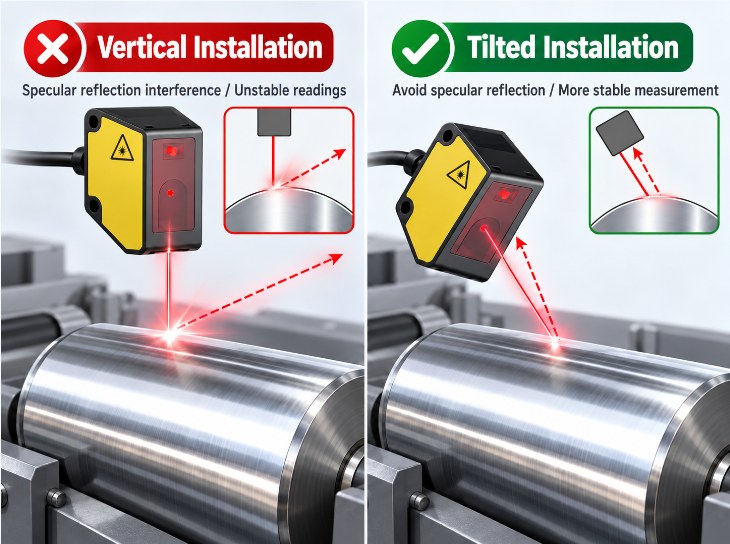
In precision manufacturing and automated production lines, laser displacement sensors (triangular reflection type) are often used to measure distance, thickness, and surface profile. However, when the measured object is highly reflective metal (such as polished stainless steel shafts, aluminum cylindrical rollers, or chrome-coated surfaces), many engineers will encounter a headache-inducing problem: Sensor data jumps wildly, or even completely "disappears".
In such cases, veteran engineers usually offer a simple solution: Install the sensor at an angle. Why must the height of reflective surfaces be installed at an angle? The core of this lies in the physical conflict between the triangular measurement light path and mirror reflection.
I. In-depth Analysis: The "Dead Spot" of Triangular Measurement Light Path
The working principle of the triangular reflection type laser displacement sensor relies on the triangular relationship in geometric optics. The laser emitter inside the sensor emits a beam of laser (incident light) onto the surface of the measured object, which is reflected, and the reflected light passes through the receiving lens and focuses on the internal photoelectric element (such as CMOS or PSD). Due to a fixed angle between the incident light and the receiving light path (baseline), when the object's distance changes, the position of the light spot on the photoelectric element will also move, thereby converting the distance.
The prerequisite for this system to work properly is that there must be sufficient light entering the receiving lens.
Common surfaces (such as rough metal, plastic, or paper) experience diffuse reflection, where light scatters in all directions, and the receiving lens always gets a share. However, the reflective surface of a cylindrical metal object is like a convex mirror, resulting in mirror reflection - the incident angle is equal to the reflection angle.
When the sensor is installed vertically (or at a specific angle) towards the highly reflective surface, the laser beam will be "perfectly" reflected to another direction, avoiding the field of view of the receiving lens. The receiving end does not receive light, falling into the "mirror reflection blind zone", resulting in erratic output data or immediate alarm.
In addition, the cylindrical surface itself has curvature, and the incident angle of the light beam changes at different positions, causing the reflection light spot to severely elongate and deform on the cylindrical surface, further exacerbating signal instability.
II. Solution One: Install at an Angle to Break the Geometric Symmetry of Mirror Reflection
Since the light has been "popped" away, let's change the direction of the light path. By tilting the sensor by a certain angle (usually between 10° and 30°, with 15° being the commonly used empirical value), for the solution to the mirror reflection blind zone, it is the most direct and effective method.
The principle of tilting:
Breaking the mirror reflection angle: After tilting, the incident light no longer reflects along the original path or in a specific symmetrical angle. The strong light beam of mirror reflection will deviate from the receiving lens, while the originally weak diffuse reflection (or surface minor flaws resulting in scattered light) will have the opportunity to enter the receiving lens.
Avoiding the focus of the cylindrical surface: For the cylindrical surface, tilting installation can avoid the light beam precisely focusing at the vertex (focus) of the cylindrical surface and reflecting out, allowing the receiver to capture the scattered light reflected from the cylindrical side.
Practical suggestions:
During on-site installation, leave some rotation margin on the sensor bracket. During the debugging process, slowly rotate the sensor angle (pitch angle or deflection angle), and observe the stability and signal strength indication of the sensor output to find the angle with the most stable data and strongest signal.
III. Solution Two: Select "Multi-Reflection Receiving Type" Sensor
If the on-site space is limited, the sensor cannot be tilted installed, or the diameter of the cylindrical surface is too small and the reflectivity is extremely high, and only tilting cannot obtain a stable signal, then a hardware solution needs to be changed - select a multi-reflection receiving type (or dual-receiving type) laser displacement sensor.
Multi-reflection receiving principle:
These sensors are internally equipped with two (or more) receiving lenses and photodetectors at different angles.
One receiver (usually facing directly) is specifically responsible for receiving the regular diffuse reflected light;
The other receiver (usually placed at a larger angle on the side) is specifically designed to capture the specular reflected light generated by highly reflective objects.
Regardless of whether the measured object reflects diffusely or specularly, and regardless of the sensor installation angle, at least one receiver can capture a strong enough reflection light signal. This hardware-level "double insurance" design enables the sensor to achieve stable measurement when dealing with glass, polished metals, and coated materials without deliberately tilting.
IV. Summary and Selection Suggestions
Solution Applicable Scenarios Operation Points/Prerequisites
Tilted Installation (10°~30°) Regular highly reflective metals, medium-diameter cylindrical surfaces Minimum cost. A tunable bracket needs to be reserved, and the best scattering angle should be found on-site.
Multi-reflection Receiving Sensor Spaces with limited space, very small cylindrical surfaces, extremely high reflectivity (such as mirrors) Higher cost. Hardware dual receiving, extremely tolerant of installation angles.
Change Light Source Wavelength Particular metals (such as copper, aluminum) absorb different wavelengths One can try blue light laser sensors. Blue light has a better scattering effect on some metal surfaces than red light.
In summary, measuring highly reflective metal cylindrical surfaces is essentially a struggle with the optical specular reflection law. Tilted installation is the most economical physical solution, while the multi-reflection receiving sensor is a more advanced and worry-free technical reduction. Understanding how the light path works allows you to turn "imprecise measurement" into "precise measurement".
Rihuan Sensing provides triangular reflection and multi-reflection receiving laser displacement sensors, optimizing the light path for high-reflective metals, curved surfaces, and complex surfaces. The products support small light spots and multiple range selections, suitable for shaft outer diameter runout, surface profile, and precise displacement measurement. Welcome to follow Rihuan Sensing to obtain professional technical selection and on-site debugging guidance.
