Today, Wuxi Rihuan Sensor Technology Co., Ltd. introduces the concepts of cascading and splicing safety light curtains and explains how two short light curtains can be used to protect an oversized opening.
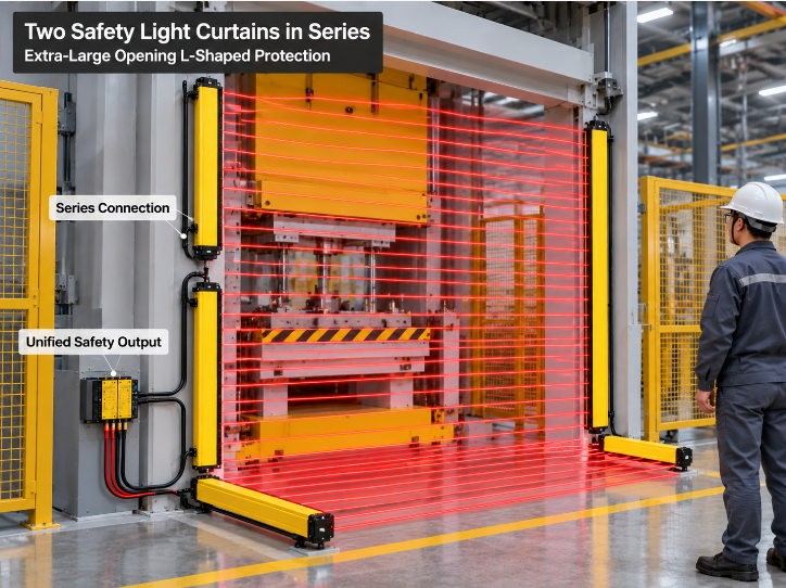
In industrial applications, when the height of an opening in a hazardous area exceeds the maximum protective height of a single safety light curtain, one unit alone cannot provide complete coverage. Simply combining two independent light curtains can result in complicated wiring, increased costs, and even safety function failures caused by optical interference between the units.
The standard solution is cascading (Cascade), also referred to as splicing in some applications. Multiple light curtains are connected in series to form one logically unified, extended protective field, sharing a single pair of safety outputs. This architecture provides comprehensive protection for oversized openings with a simplified system design.
1. Master-Slave Architecture: Host and Guest Roles
The core of a cascaded system is its master-slave architecture. Within a cascade chain, only one device—the Host (master unit)—is directly connected to the machine's safety control circuit, such as a safety relay or safety PLC. Its OSSD (Output Signal Switching Device) outputs represent the safety status of the entire cascaded system.
Subsequent Guest (slave units) are connected sequentially to the Host or to the preceding Guest. They do not provide independent safety outputs.
For example, a typical three-unit cascade is connected in the following order:
Host → Guest 1 → Guest 2
The Host connects to the control cabinet, Guest 1 connects to the Host, and Guest 2 connects to Guest 1. The entire cascaded system functions externally as one extended safety light curtain. If any section of the protective field is interrupted, the Host's OSSD outputs switch to the OFF state, triggering the machine's stop function.
Key limitation: The total length and number of beams in a cascade are restricted by the product specifications. Some systems support a maximum of three cascaded light curtains, while certain models support up to four pairs. Only models from the same product series that are explicitly designed for cascading should be used. Never hardwire devices from different brands or product series together.
2. Synchronization Wiring: Daisy-Chain Connections via M12 Interfaces
Physical cascading relies on dedicated system interfaces or interconnecting cables. Although pin assignments differ between manufacturers, the basic connection logic remains similar.
SICK systems: The Host typically uses an 8-pin system interface, while Guest units use a 5-pin system interface. The Host's 5-pin expansion interface connects to the Guest's 5-pin system interface.
Banner systems: Double-ended detachable connectors (RD cordsets) are used for daisy-chain connections, with transmitters connected to transmitters and receivers connected to receivers. All receivers share the OSSD outputs of the Host receiver.
General rule: Cascade cables must be connected with the correct wire colors and pin-to-pin assignments. Incorrect wiring—for example, connecting a Host transmitter cable to a Guest receiver—can compromise the safety function.
Scan codes or beam coding are essential for preventing optical interference within a cascaded system and between adjacent systems.
In a cascade, scan codes are often automatically alternated. For example, if the Host uses Scan Code 1, Guest 1 may use Scan Code 2, while Guest 2 returns to Scan Code 1.
Without beam coding, a receiver may mistakenly identify signals from another transmitter as its own, potentially compromising the reliability of the safety function.
3. Overlap at the Junction and Minimum Spacing Requirements
When two light curtains are used to protect an oversized opening, their protective fields cannot simply be placed end to end without verification. The following requirements must be met.
3.1 Protective Field Overlap
The protective fields of the two light curtains should overlap vertically to ensure that no uncovered gap remains. The overlap must account for installation tolerances and potential displacement caused by vibration.
If a physical gap exists at the junction, a person's hand or a tool could pass through without interrupting a light beam, creating a genuine protection gap.
Although a cascaded system shares a common pair of OSSD outputs, the beams in each section remain physically separate. Any area without beam coverage represents a real safety vulnerability.
3.2 Minimum Spacing Between Adjacent Light Curtains
When two light curtains are installed parallel to each other and facing the same direction, rather than arranged in a perpendicular configuration, a minimum separation distance must be maintained to prevent optical interference.
Taking Pilz specifications as an example, the minimum distance between two parallel light curtains without beam coding depends on the crossing distance between the transmitter and receiver.
When the crossing distance A is less than 3 m: the minimum separation distance is D = 0.131 m.
When A is greater than or equal to 3 m: D = A × tan 2.5°.
When beam coding is used, the required spacing is also calculated based on A. For A less than 3 m, the minimum spacing remains D = 0.131 m under the cited conditions.
Rockwell provides the following empirical formula:
S > 0.026 × D
Where S is the separation distance and D is the operating distance, according to the referenced application guidance.
Always consult the installation manual for the specific model to confirm the applicable formula and measurement definitions.
3.3 Accumulation of Response Time in Cascaded Systems
In a cascaded system, signals pass through multiple stages, so the total response time may be longer than that of a single light curtain.
Banner documentation includes a dedicated section on calculating the response time of cascaded light curtains.
After cascading, the total system response time must be used to recalculate the safety distance according to the applicable formula:
S = K × T + C
If the increased response time is ignored, the light curtain may be installed too close to the hazardous area, allowing a person to reach the danger zone before the machine has fully stopped.
4. Cascading vs. Independent Splicing: Which Should You Choose?
| Comparison | Cascading (Cascade) | Independent Splicing |
|---|---|---|
| OSSD outputs | One shared pair of outputs for unified safety logic | Each unit has independent outputs |
| Wiring complexity | Lower; daisy-chain connections | Higher; each unit is wired separately into the safety circuit |
| Optical interference | Scan codes may alternate automatically, reducing interference risk | Different scan codes may need to be configured manually |
| Response time | May increase as signals pass through multiple stages | No cascade-related accumulation between independent units |
| Typical applications | Large openings and L-shaped or U-shaped protective zones | Separate, independently controlled hazardous points |
For oversized openings, cascading is often the more straightforward solution. It reduces wiring, unifies the safety logic, and allows multiple units to function externally as one extended light curtain.
However, the increased response time must be taken into account, and the safety distance must be recalculated accordingly.
If extremely fast response is required, or if each protective section needs independent control, independent splicing may be more appropriate.
The essence of cascading is not simply connecting two light curtains together. It is enabling multiple units to operate reliably as one coordinated safety system.
The master-slave architecture forms the backbone; synchronization wiring and scan codes provide coordinated operation; and the overlap and spacing at the junction establish the fundamental protection requirements. All three are essential to avoiding blind spots and unintended safety function failures.
Wuxi Rihuan Sensor Technology Co., Ltd. offers safety light curtains that support cascading and series connections, featuring a clear master-slave architecture and automatic scan-code alternation to help prevent optical interference within cascaded systems and between adjacent systems.
Follow Rihuan Sensor for professional cascade solution design and product selection support.
