Today, Wuxi Rihuan Sensor Technology Co., Ltd. will introduce to you the miniature (M5/M8) proximity switches: Why is the body not damaged, but the cable root always breaks?
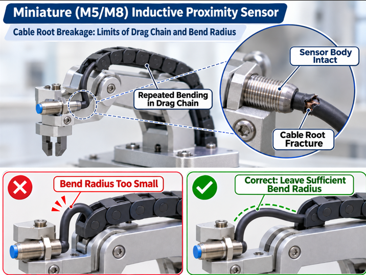
In small mechanical hands, precision fixtures, or high-frequency reciprocating slide tables, M5 and M8 types of miniature inductive proximity switches are widely used. Their size is small enough to fit into narrow installation spaces. However, there is a very typical phenomenon on-site: The sensor body is intact, the shell is not cracked, and the sensing is normal, but only the cable root (the outlet position) breaks, the signal is intermittent, and it has been replaced one after another, and the problem keeps recurring.
This is not due to the poor quality of the switch, but the cable of the miniature sensor is itself under mechanical stress beyond its design limit.
1. The cable of the miniature sensor is inherently "thin"
The volume of M5 and M8 sensors determines that their outlet cannot be thick. Taking the M8 proximity switch as an example, the standard cable's outer diameter is usually around 3.6mm, and the internal conductor's cross-sectional area is only at the 0.14mm² level. The thinner the wire diameter, the smaller the diameter of a single copper wire, and the weaker the ability to resist fatigue fracture when repeatedly bending.
Ordinary sensor cables use a single or a small amount of thick copper wire structure. In static installation or occasional bending scenarios, this structure is not a problem. However, in scenarios such as mechanical hand joints and reciprocating slide tables with high-frequency and large-angle bending, the copper wire will repeatedly undergo "bending - stretching - rebound" cycles. The lattice structure of a single thick copper wire gradually develops micro-cracks under continuous stress, and eventually completely breaks. The result is that the outer protective cover looks intact, but the internal copper core has broken, and the signal intermittently loses.
2. The root is the "dead spot" with the most stress
The location where the cable breaks is almost always concentrated at the outlet root - the junction between the sensor shell and the cable.
This is due to the geometric discontinuity. When the cable extends vertically from the sensor tail, if the installation space forces the cable to make a sharp turn near the root (such as along the equipment side wall or around adjacent mechanisms), the bending point is "stuck" in the position close to the shell. This position has a very small bending radius, even approaching zero. Every mechanical movement, the root of the cable is subjected to a near-acute-angle bending destruction.
And the installation space of the miniature sensor is often extremely cramped. M5/M8 sensors are already installed in narrow fixture gaps or the end of the mechanical hand, and the outlet direction has almost no adjustment room. The cable is forced to bend hard at the root very commonly.
3. Correct solution: Three-layer protection from selection to fixation
The first layer: The cable material must be upgraded to high flexibility
Ordinary PVC cables or single-strand copper core cables are not suitable for high-frequency bending scenarios. High-flexibility cables with multiple strands of ultra-thin copper wires should be selected. The significance of the multi-strand structure lies in: When bending, the individual strands of thin copper wires can slide relative to each other, distributing the concentrated stress to the entire conductor cross-section instead of being borne by a single thick copper wire alone. Industry standards require a bending radius of ≥10 times the cable's outer diameter for drag chain cables, and high-flexibility levels can reach 5D to 10D. For the M8 sensor with an outer diameter of approximately 3.6mm, this means the bending radius should be at least 18mm or more, and high-flexibility cables can be relaxed to the 18-36mm range.
The second layer: The outlet direction should be "straight" and not "diverted"
If the installation space allows, prefer to use the miniature sensor with a 90° elbow outlet. For straight-out-line sensors installed at corners, the cable is forced to make a sharp turn at the root; elbow-out-line allows the cable to extend laterally from the side and directly align with the equipment wall for wiring, and the root does not need to bear the sharp bend stress.
If only a straight-out-line model can be used, during installation, a natural curved transition section must be reserved at the cable root, and it must not be made to immediately bend in another direction right after touching the shell. After reaching the line outlet, maintain a straight line for a certain distance (at least 2-3 times the diameter of the wire), and then start bending.
Third layer: The root part requires additional stress release structures.
Some sensor manufacturers have designed thickened buffer tail sleeves at the root of the line outlet. Their function is to make the transition from the rigid housing to the flexible cable at the root not be a "hard impact". The tail sleeve forms an arc-shaped buffer area at the root, dispersing the bending stress from a sharp angle that is concentrated at one point to a curved line, significantly reducing the probability of the root insulation layer cracking and the copper core breaking.
Four. If it has already broken, how to remedy it?
After the root of the cable breaks, it is not recommended to re-weld or press-connect on-site. The internal conductors of the micro sensors are extremely thin, and the strength and insulation reliability of the repair joints in the field cannot be guaranteed. They will fail again under high-frequency vibration soon. The correct approach is to replace the entire sensor or use the model with M8 connectors - the connector version allows for the separate replacement of the cable, while the sensor body can continue to be used, reducing long-term maintenance costs. The di-soric series of micro sensors provides two out-line methods with M8/M12 connectors and built-in cables, and in high-frequency bending scenarios, the connector + replaceable cable solution is more practical.
Summary
The cable of the micro proximity switch has broken. Essentially, the extremely fine conductor has endured extremely high fatigue stress under a very small bending radius. When selecting the model, make sure to choose multi-strand flexible cables with high flexibility. During installation, avoid sharp bends at the root. If necessary, use the bent pipe outlet or connector version - if these three steps are followed, the cable lifespan can be extended from a few weeks to several years.
Rihuan Sensing offers M5, M8, etc. micro inductive proximity switches. They can be optionally equipped with high-flexibility cables and bent pipe outlet structures, suitable for high-frequency bending scenarios such as small robotic arms and precision fixtures. If you need guidance on the selection and wiring of micro sensors, please follow us at Rihuan Sensing.
