Today, Wuxi Rihuan Sensing Technology Co., Ltd. will introduce to us what limitations the "long cable wiring" of photoelectric sensors has? - The dual challenges of voltage drop and interference.
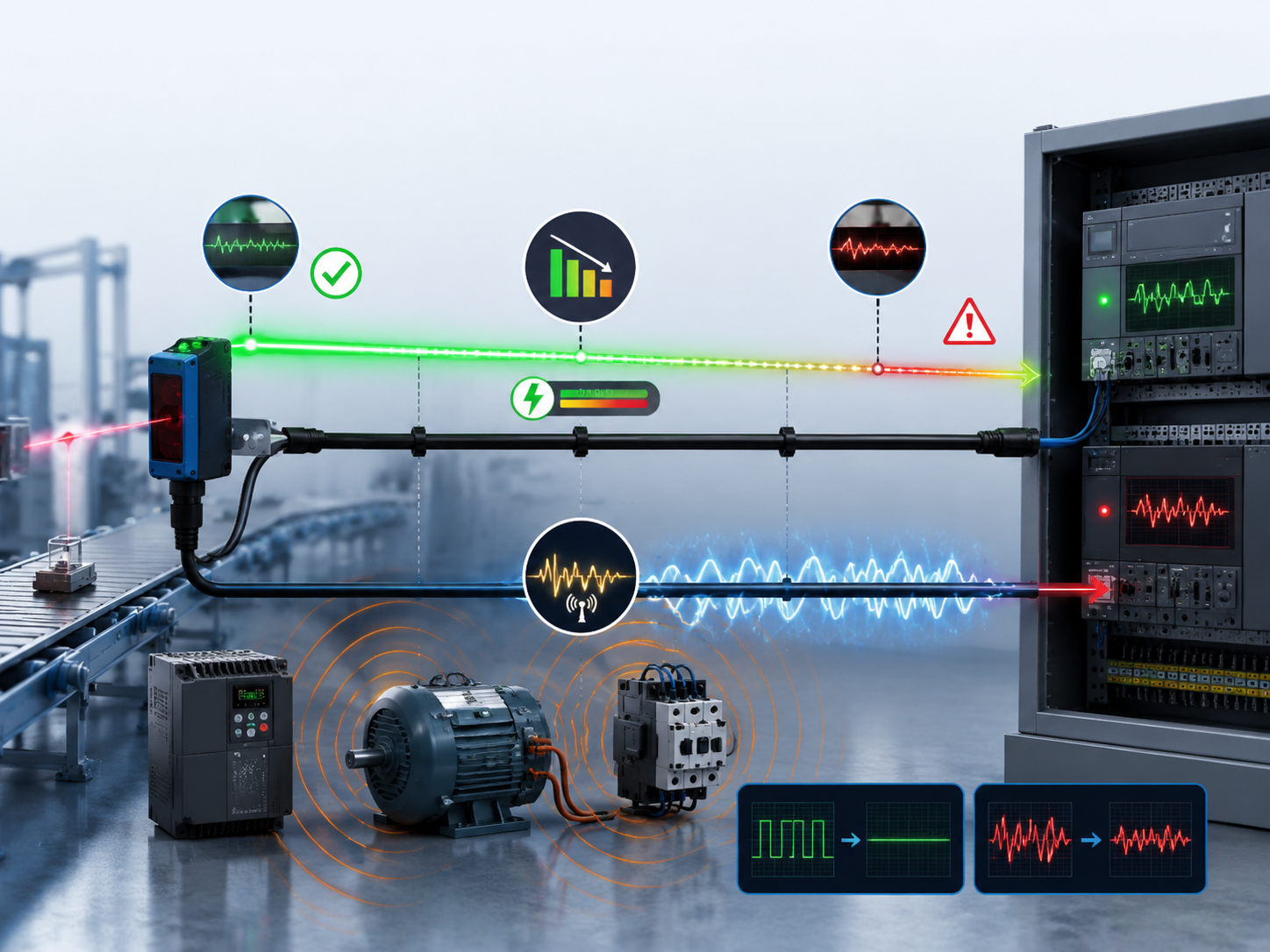
In industrial settings, the installation locations of control cabinets and sensors are often quite far apart, and long cable wiring is a common requirement. However, many people overlook a crucial issue when extending the cables: cables are not infinitely extendable. When the cable length exceeds a certain limit, both voltage drop and electromagnetic interference will occur simultaneously, causing the sensor signal to become unstable or even completely fail.
1. Voltage Drop: The longer the cable, the lower the voltage.
Optoelectronic sensors typically require a stable direct current voltage supply (commonly 12-24V DC). The copper wire itself has resistance, and the longer the cable and the smaller the cross-sectional area, the greater the resistance. When current flows through the wire, a voltage drop occurs on the wire.
Actual case: A packaging line used 0.3mm² wires to power a 24V sensor. Due to the excessively long cable, the actual working voltage of the sensor only reached 18V, resulting in frequent malfunctions. After replacing the cable with 0.75mm² wires, the failure rate decreased by 90%.
The calculation formula is: ΔU = I × R = I × (ρ × L / S), where ρ is the resistivity of copper (approximately 0.0175 Ω·mm²/m), L is the length of the cable, and S is the cross-sectional area of the conductor.
If the minimum operating voltage of the sensor is 10V and the supply voltage is 24V, the maximum allowable line voltage drop is 14V. The longer the cable and the greater the current, the more severe the voltage drop will be. When the voltage drop is too large, if the actual operating voltage of the sensor is lower than its minimum operating voltage, there will be phenomena such as the indicator light being able to light up but the output cannot drive the load, and the signal being intermittent, which is known as "false illumination but actual failure".
Solution
Select cables with a larger cross-sectional area (such as 0.3mm² or larger)
Calculate the total pressure drop and ensure that the voltage at the sensor end remains within its rated operating range.
II. Electromagnetic Interference: The longer the cable, the stronger the antenna effect
Another issue faced by long cables is electromagnetic interference. The photoelectric sensor generates electrical signals through high-frequency modulation. At high frequencies, a single wire is equivalent to an inductor. The longer the cable, the stronger the electromagnetic radiation interference received.
When the signal lines are laid side by side with strong current lines such as those of the frequency converter and motor power supply, or are placed in the same conduit, electromagnetic induction may cause the sensor to malfunction. Long cables are particularly susceptible to this effect.
Typical symptoms:
The target object is stationary, but the sensor output is frequently on and off.
When the equipment is running a high-power motor, the sensor signals are jumping erratically.
There is no obvious obstruction, but the grating frequently triggers false alarms.
Anti-interference measures:
Separate wiring: Signal lines and power lines must be routed in separate conduits. Avoid parallel wiring and maintain a right angle when crossing.
Using shielded cables: When conducting long-distance wiring, the signal lines should be replaced with shielded cables, with the shield layer grounded at one end.
Keep a distance from high-voltage lines and power lines: Avoid parallel wiring or using the same wiring conduit.
III. Differences between NPN and PNP in Long-Distance Transmission
When conducting long-distance wiring, different output types of photoelectric sensors exhibit different performances:
Open-circuit collector output of NPN: It is recommended to use this option for transmission distances exceeding 100 meters. When the NPN output is conducting, it pulls the signal line down to 0V, providing stronger driving capability and better signal integrity during long-distance transmission.
PNP output: During long-distance transmission, the high-level signal is prone to be affected by the line capacitance and leakage current, resulting in more significant signal attenuation.
The specification sheet of some photoelectric sensors clearly states: When extending the cable, the full length can be extended to 100 meters by using a cable with a cross-sectional area of 0.3 mm² or larger. However, this is only the electrical limit. In actual use, interference factors also need to be taken into consideration.
IV. What to do if the wiring distance exceeds 100 meters?
If the wiring distance at the site exceeds 100 meters, the following several solutions can be chosen:
Solution 1: Increase the cross-sectional area of the cable
Using larger cross-sectional diameter wires (such as 0.75mm² or 1.0mm²) can effectively reduce line resistance and minimize voltage drop. However, the thicker the cable, the higher the cost and the greater the difficulty in wiring.
Option 2: Relay Amplification
An amplifier or intermediate relay should be added between the sensor output end and the controller to re-amplify the signal and then continue to transmit it.
Option Three: Switch to optical fiber sensors
Optical fiber sensors transmit light signals through optical fibers, which are not affected by electromagnetic interference and have a long transmission distance (up to several kilometers). They are the preferred solution for long-distance detection.
Option Four: Wireless Transmission
In situations where wiring is extremely difficult or the distance is particularly long, a wireless sensor solution can be considered.
V. Engineering Suggestions
Cable Length Recommendation Measures
≤2m Standard factory cables can be used directly
2 - 20m Use cables with a cross-sectional area of 0.3mm² or larger. Ensure they are routed separately from power lines
20 - 100m Use shielded cables. Prioritize NPN output. Check the terminal voltage
≥100m Add repeater amplifiers, switch to optical fiber sensors, or adopt wireless solutions
Summary in one sentence: The core of long-cable wiring is "consider voltage drop, prevent interference, and select the correct output." The longer the cable, the more attention must be paid to these three issues - otherwise, even if the sensor is installed perfectly, the signal will not be transmitted back.
Welcome to follow us at Rihuan Sensing to obtain more reliable photoelectric detection solutions.
