Today, Wuxi Rihuan Sensor Technology Co., Ltd. will introduce to you how to wire the cables of the safety grating? - The signal lines and power lines must be routed separately through the wiring trough.
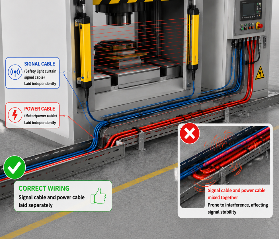
After the safety grating was installed, the indicator light was normal and the optical axis was aligned properly. However, during the operation of the equipment, false alarms or signal loss occurred frequently. In many cases, the problem did not lie in the grating itself, but in the wiring method of the cables.
The output and input signals of the safety barrier are weak electrical signals, while the power lines of equipment such as frequency converters, motors, and contactors are strong electrical circuits. When the signal lines and power lines are laid side by side in the same conduit, the strong current flowing in the power lines will generate a strong electromagnetic field, which induces interference voltages on the signal lines through inductive coupling. This interference is sufficient to cause the output signal of the safety barrier to malfunction - for instance, the equipment suddenly stops running when there is no obstruction; or in a more dangerous situation - the light beam is blocked, but the signal fails to be correctly recognized due to the interference.
1. Why must they be separated?
The signal lines of the safety grating (including the OSSD safety output line, CP synchronization signal line, etc.) transmit weak signals in the milliampere range, which are highly susceptible to external electromagnetic interference. While the power lines carry large currents in amperes, when they run in parallel in the same cable trough, the electromagnetic field generated by the power lines will induce stray voltages on the signal lines.
The consequences include:
The raster output signal is jittery, causing intermittent malfunctions and shutdowns of the equipment.
The device does not stop after blocking the light beam (the signal is overwhelmed by interference)
The synchronization signal was disturbed, causing the transmitter and receiver to fail to work together properly.
In severe cases, it may damage the internal circuits of the grating.
II. Correct Wiring Method
1. Slot-based laying, different line slots
The signal lines and power lines should be laid in separate conduits. If it is not possible to set up separate conduits due to the conditions, at least partitions should be used in the same conduit to physically separate the strong and weak electrical lines. Meanwhile, the two types of cables should have distinct markings for easy maintenance and troubleshooting in the future.
2. Maintain sufficient distance
The distance between the signal line and the power line should be no less than 30 cm. If the on-site space is limited and this distance cannot be met, shielded cables should be selected and reliably grounded to make up for it.
3. Use shielded cables
The signal lines of the safety barrier should preferably use twisted-pair shielded cables. The shield layer should be grounded at one end (usually at the control cabinet end), to avoid forming a ground loop. The higher the coverage of the shield layer, the stronger the anti-interference ability.
4. Avoid walking in a straight line
If the signal lines and power lines must cross in space, they should be crossed vertically rather than laid parallel to minimize the area of induced coupling.
5. Separate piping for signal lines
For particularly critical safety signal lines, it is recommended to lay them in separate protective conduits, and there should be no other power lines inside the conduits.
III. Other Wiring Considerations
Power Independence: It is recommended to use an independent 24V power supply for the safety photoelectric sensor to avoid sharing the same power source with high-power equipment such as frequency converters and servo drives.
Cable length: Do not privately extend or shorten the transmission line of the grating. If you need to extend it, you must use a shielded transmission line and ensure proper grounding.
Bending radius: The bending radius of the cable should not be less than the minimum value specified in the product manual. Excessive bending may cause the internal core wires to break.
Junction handling: Unused output cables (such as the other channel in a dual-output setup) should be insulated to prevent short circuits.
IV. Wiring Color Reference
The standard wiring colors for safety grilles are typically:
Brown: Positive terminal of the power supply (DC 24V)
Blue: Negative terminal of the power supply (0V)
Black/White: Safety Signal Line (OSSD1/OSSD2)
The specific color definitions are subject to the product manual. Please double-check before connecting the wires.
V. Summary
Key Points for Wiring Specific Requirements
Separation of Cable Trays Signal lines and power lines should be laid in separate cable trays, or separated by partitions.
Minimum Spacing Spacing between signal lines and power lines should be ≥ 30 cm.
Cable Type Preferred choice is twisted shielded cables, with the shielding layer grounded at one end.
Crossing Method When crossing is necessary, it should be done vertically rather than horizontally.
Independent Power Supply It is recommended to use an independent 24V power supply, not shared with high-power equipment.
Wiring of Safety Photogates is not a matter of "it just needs to be connected". If signal lines and power lines are mixed in the same cable tray, it's like tying a telephone line to a high-voltage wire - the phone line is full of noise, and no information can be transmitted clearly. Once the signal of the safety photogate is interfered with and drowned out, it will not stop when it should, and the consequences will be unimaginable.
The safety grating products of Rihuan Sensor are equipped with high shielding rate twisted-pair signal cables, which effectively suppress electromagnetic interference. The product manual provides detailed wiring and layout guidance, helping users avoid interference risks during the installation stage. Welcome to follow Rihuan Sensor to obtain more reliable safety protection solutions.
